Arduino – Analog Input : How Potentiometer works?

Yann KIDSHAKER 18 mars 2026
Introduction
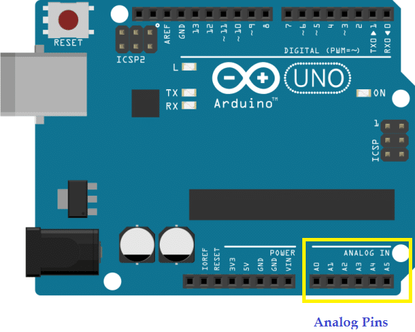
evive has 10 analog input pins under its magic lid and Arduino Uno has 6 of them. The converter has a 10-bit resolution; therefore, it returns 210, i.e. 1024 values, these values being integers from 0 to 1023. The main function of the analog pins for most Arduino users is to read analog input from analog sensors.

How to read analog value?
To read analog input from an analog pin in Arduino IDE, you have to use analogRead(pin) function.
analogRead(pin) function reads the value from the specific analog pin. The output is an integer value between 0 and 1023 (Due to a 10 bit analog to digital converter), which is mapped between 0 and 5 volts input voltage. This yields a resolution between readings of 5 volts / 1024 units or, .0049 volts (4.9 mV) per unit.
It takes about 112 microseconds (0.000112 s) to read an analog input, so the maximum reading rate is about 9,000 times a second.

Potentiometer
The potentiometer, commonly referred to as a “pot”, is a three-terminal mechanically operated rotary analog device which can be found and used in a large variety of electrical and electronic circuits. They are passive devices, meaning they do not require a power supply or additional circuitry in order to perform their basic linear or rotary position function.
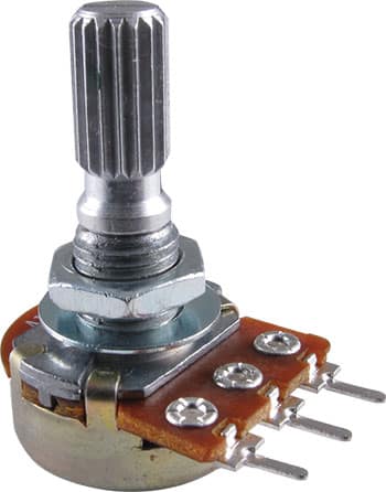
The term potentiometer and variable resistor are often used together to describe the same component, but it is important to understand that the connections and operation of the two are different. However, both share the same physical properties in that the two ends of an internal resistive track are brought out to contacts, in addition to a third contact connected to a movable contact called the “slider” or “wiper”.
When used as a potentiometer, connections are made to both ends as well as the wiper, as shown. The position of the wiper then provides an appropriate output signal (pin 2) which will vary between the voltage level applied to one end of the resistive track (pin 1) and that at the other (pin 3).
The potentiometer is a three-wire resistive device that acts as a voltage divider producing a continuously variable voltage output signal which is proportional to the physical position of the wiper along the track.
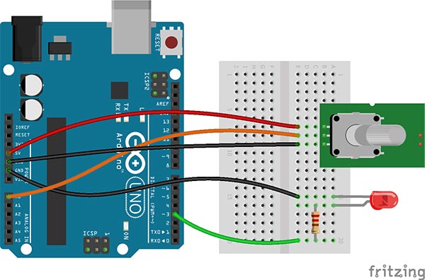
Circuit Diagram
We will measure the output voltage of the potentiometer on the serial monitor on analog pin A0 and glow the LED with the mapped PWM. Follow the circuit:
- Connect the left pin of the potentiometer to GND.
- Connect the right pin of the potentiometer to 5V.
- Connect the middle pin of the potentiometer to Analog pin A0.

Arduino IDE Program
Given below is the code for reading potentiometer output value on Serial Monitor and glowing the LED. Since analog value read is between 0 to 1023 and PWM output value is between 0 to 255, we have to map them both. Here is how you do it:
PWM Value = Analog Value / 4